Highlights
- According to Eurocode 3 fully integrated in the standard SCIA Engineer steel design environment.
- Derivation of effective shape, including distortional buckling for internal and edge stiffeners and double edge folds.
- Effective section of library and general cross-sections: support for any arbitrary shape, also when imported from CAD software.
- Advanced checks for local transverse forces, also for sections with stiffened webs.
- Special purlin design checks including derivation of free flange geometry, checks under gravity and uplift loading.
- Accurate and extensive checks according to the relevant parts of EN 1993-1-3, EN 1993-1-5 and EN 1993-1-1.
The cold-formed steel design module for EN 1993 is an extension to the module sensd.01.en Steel design. It enables you to design cold-formed steel elements according to the European standards EN 1993-1-3, EN 1993-1-5, and EN 1993-1-1.
- Both section and stability checks are supported: these are executed the same way as for conventional steel members;
- Built-in decision mechanisms determine which code articles are to be used, based on the geometry, internal forces, presence of sheeting and other model parameters.
- Reduced effective section properties due to local and distortional buckling are taken into account in all checks;
- Specialised design procedures for failure under local transverse forces and for purlins attached to sheeting are applied as specified in the code.
Benefits
- sensd.02 analyses a wide variety of open steel sections for local buckling effects;
- Effective cross-sections are derived for compression, strong- and weak-axis bending; these are then used in the general steel code checks, where necessary, and can be displayed graphically.
- The effective shape derivation takes into account distortional buckling of edge and intermediate stiffeners and double edge folds;
- The intelligence behind the effective section calculation increases productivity by requiring very limited user input;
- The Profile Library contains a wide variety of products from cold-formed steel manufacturers; the dimensions of these profiles can also be edited by the user, thus extending the Profile Library with more products;
- Using General Cross-section Editor (included in module sen.05), users can define custom cross-sections; including import from dxf and dwg files;
- The supporting effect of steel sheeting is taken into account for economical purlin design. A library of sheeting products from popular manufacturers is also available.
- An automated optimisation procedure (AutoDesign) in the steel design functionality selects suitable profiles depending on (1) the internal forces in the structure and slenderness of members and (2) the set of preferred profiles selected by the user.

How does it work?
This unique feature of SCIA Engineer analyses a cross-section geometry to recognize internal elements, outstands, edge and intermediate stiffeners, and performs a comprehensive calculation according to the rules given in the specialized standard EN 1993-1-3:2006/AC:2009.
- You assign cold-formed steel cross-sections to members in the 3D model;
- These cold-formed steel profiles are analysed. Their walls are classified as internal, symmetrical/asymmetrical outstands (with or without intermediate reinforcement) and rigid parts; for general cross-sections the automatically determined classification may be adapted;
- It is checked whether the modelled cross-section complies with the limitations of the code (in terms of width-to-thickness ratios, adequate size of stiffeners, etc.);
- The effective-width analysis approach is applied for each of the profile elements; reductions due to localised buckling effects are taken into account;
- Notional widths are used in the determination of effective section properties;
- Local buckling is taken into account by reducing the widths of straight parts; distortional buckling is taken into account by reducing the effective thickness of the stiffeners.
- Iterations may be performed to establish a more accurate geometry of the stiffeners (stiffener iterations) and a more accurate stress distribution in the cross-section (full-section iterations);
- A reduced section geometry is derived for cases of pure bending and pure compression. Stress gradients for both weak- and strong-axis bending are correctly generated. Interaction of load effects is taken into account as per EN 1993-1-1 at the level of section and stability checks;
- For sections from the profile library, you may select to directly use effective section properties provided by the manufacturer. In this case, effective section calculations will not be performed, and catalogue values will be used;
- With the established cross-section properties and shifts in neutral axes, section and stability checks are performed according to EN 1993-1-3;
- To improve stability, additional elements may be included in the model - sheeting diaphragms, lateral-torsional buckling restraints, web stiffeners;
- Special considerations are followed in the design of purlins restrained by sheeting (according to Chapter 10 of EN 1993-1-3);
- Serviceability limit state provisions are applied based on the rules for conventional steel members. Deflections for both variable and total loads are checked; camber can also be applied on the CFS members (either input manually or determined by the software).
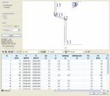
Average yield strength
In cases that fulfil the requirements of the code (e.g. fully effective sections under axial compression) the average yield strength will be taken into account when deriving the resistance of a member. Only the production method (roll forming vs. press braking) needs to be specified; the correct value of the k coefficient will be taken into account accordingly.
Steel core thickness
SCIA Engineer automatically reduces the nominal thickness defined (or specified in the manufacturer's catalogue when the profiles are taken from the profile library) to take into account the thickness of corrosion protection layers. By default, a reduction of 0.04 mm is taken into account, which corresponds to the standard galvanisation practice, i.e., 275 g/m2 of zinc coating on both sides of the profiles.
Corner roundings
If the analysed cross-section has a standard shape, SCIA Engineer correctly takes into account the presence of rounded corners in the profiles. Standard shapes are provided in the profile library:
- common shapes, such as channels, U-, point-symmetric and asymmetric Z- (with or without edge stiffeners), Σ-, Ω-sections;
- special shapes, such as point-symmetric and asymmetric Z-sections with inclined edge stiffeners, channel and Σ-profiles with complex (2-fold) edge stiffeners, Sigma shapes with inclined flanges or arched segments;
- paired sections, such as back-to-back C's, back-to-back Σ's.
For profiles that do not fit within these limitations, corner roundings are ignored and the sections are represented by flat elements.
Purlin design
The special checks for purlins restrained by sheeting are performed for profiles that meet the requirements of Chapter 10 of EN 1993-1-3. Increased load-bearing capacity is obtained, because some standard design checks need not be performed for such members (e.g. for lateral torsional buckling, combined stability in axial compression and bending).
The module allows for the flexible support coming from diaphragms to be taken into account as rotational spring at the point of fastening.
- The analysis correctly takes into account the position and stiffness of roof diaphragms. Depending on the load case, a diaphragm is attached to the compression side or to the tension side of a member and that leads to different stability behaviour.
- The geometry of the free flange is determined, as well as the magnitude of the fictitious lateral load.
- From the calculated buckling resistance of the free flange, a suitable spacing between the anti-sag bars can be determined.
Supported cross-sections
- Standard cross-sections from the profile library (see above);
- Thin-walled geometric sections (introduced by means of a concept shape and wall dimensions and thickness);
- Paired cold-formed steel profiles (e.g. a back-to-back Sigma section);
- General thin-walled sections or general polygons with thin-walled representation;
Summary of performed checks
The following section checks are performed:
- Axial tension;
- Axial compression;
- Bending moment;
- Shear force;
- Torsion (not performed in case of sufficient support from roof diaphragm);
- Local transverse forces for stiffened or not stiffened webs;
- Combined tension and bending (not performed in case of sufficient support from roof diaphragm);
- Combined compression and bending (not performed in case of sufficient support from roof diaphragm);
- Combined shear, axial force and bending moment;
- Combined bending and local transverse force.
The following stability checks are performed:
- Flexural buckling;
- Torsional and torsional-flexural buckling;
- Lateral-torsional buckling (according to EN 1993-1-1, the elastic buckling force is determined from the cubic equation of overall stability);
- For purlins, special checks for buckling of a free flange are performed according to Chapter 10;
- Combined stability -- bending and axial compression (according to the interaction equations in EN 1993-1-1 or the simplified formula in EN 1993-1-3);
- Combined stability -- bending and axial tension;
If a roof diaphragm provides sufficient support, only flexural buckling checks for the strong axis are performed.
Required modules:
- sensd.01.en