Highlights
- In the General Cross-section Editor, you can input any arbitrary cross-section shape in a graphical way, including sections composed of multiple entities and multiple materials.
- Cross-sectional characteristics are calculated and used in the 3D analysis and design environment of SCIA Engineer.
- The Profile Editor serves for the editing or adding of new profiles (with user-defined dimensions and material) that have shapes that already exist in the Profile Library.
- An extensive library of shapes exists in SCIA Engineer and can be used as a template.
- Entire manufacturer catalogues can be integrated in SCIA Engineer in this way; the profiles are then treated as SCIA Engineer's native library items.
General Cross-sections
Complex cross-section shapes can be defined via the General Cross-section Editor and later used in the analysis and design modules.
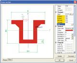
- A CAD-like GUI allows you to work with common graphical entities when introducing cross-sections: lines and curves, polygons, geometrical shapes with or without multiple holes, etc.;
- Both solid and thin walled (centreline & thickness) cross-sections can be drawn;
- Sections from the Profile Library can be inserted and combined with one another or with other shapes;
- DXF and DWG files can be imported;
- Separate parts of a general cross-section may be defined using the different methods mentioned above; the parts can then be combined to form a single shape;
- During input, drag-and-drop and numerical editing of vertex coordinates are possible, as well as copying, rotating, mirroring, filleting etc.;
- Various parts of a section may be assigned to construction stages; for example, for composite bridge cross-sections or pre-stressed elements, you can indicate which parts of the section will be activated in which phase;
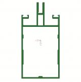
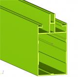
Parametrisation
Parameters can be assigned to dimensions, thus creating a parametric definition of the shape.
- Node coordinates or dimensions can be linked to user-defined parameters;
- Parameters are either values or formulas, which means that various dependencies may be defined between the section dimensions;
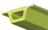
- General cross-sections are allowed in members with variable cross-sections (haunches and arbitrary members). The following picture shows a member with a variable profile, defined as a general cross-section.

Overlapping section parts
- Mixed cross-sections (steel-concrete, concrete-timber) are defined, in which parts may completely or partially overlap;
- It is possible to define a "priority value" for each section part; the part with higher priority would be taken as reference for the actual material in the areas of overlap;

Visualisation
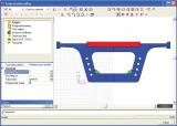
- The section is displayed both in the General Cross-section editor and Cross-section Library;
- Colour settings are used to indicate the presence of multiple materials;
- Dimension lines and additional text and descriptions can be inserted into the cross-section image.
Calculation of section properties
- The geometric properties of the section are automatically calculated (e.g. area, drying surface, inertial and section moduli, torsion properties, etc.).
- Torsional properties determined using 1D or 2D FEM discretisation and analysis, depending on whether the section is thin- or thick-walled.
Classification for steel and aluminium members
- Both thin-walled and polygonal shapes can be classified based on their slenderness.
- For class 4, effective section properties can also be calculated for General cross-section shapes.
Profile Editor
The Profile Editor allows editing the cross-section libraries in SCIA Engineer.
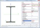

- Existing profiles are used as templates for new shapes;
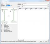
- New cross-sections and section properties are inputted in tabular form;
- Copy-Paste from external databases and spreadsheets is supported;
- Section properties (including torsional) for new cross-sections are immediately available;
- Any calculated cross-section property for both new and existing cross-sections may be manually overwritten;
- Checks of validity/consistency of user-defined data are performed to avoid user errors.
Due to the consistent use of 'form codes,' new sections are handled as built-in sections in design checks:
- Bow imperfections, buckling capacity, effective sections are derived in the same way as for existing profiles;
- Plastic checks can be performed for added sections that fall under class 1 or 2;
- Effective section properties are used for class 4 sections.
- You can overwrite buckling curves for each section.
Unlimited number of User libraries are supported. User libraries have the same properties as the System library, but allow for customisation, e.g. per project:
- User-defined fabrication methods;
- User-defined library filters can limit the number of visible sections, in order to increase productivity;
- A simple ASCII import/export allows transfer of sections from one section library to another.
Additional description data can be added per profile type:
- These may be stored in external files and called when needed;
- Multiple languages for the additional data are supported;
Required modules:
- sen.00