Highlights
- User input of number of buckling modes to be calculated.
- Results include buckling factors (ratio between the critical buckling load and the applied load) and associated deformed shapes.
- Deformed shapes can be displayed graphically for each calculated buckling mode.
- The critical buckling mode can be imported in the geometric non-linear calculation as an initial deformation (in combination with geometrical non-linear module)
This module allows determining the global critical buckling modes and buckling loads of frame structures as well as surface elements (plates and shells) under the given loading. In addition, the ratio between the buckling load and the applied load is given.
Stability calculations are used to obtain an insight into the buckling mechanisms of a structure, to calculate the buckling length of a member for use in the Code Checks, to verify if 2nd order calculations are required.
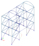
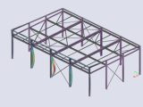
Non-linear stability analysis
This functionality allows determine the global critical buckling mode and buckling load of frame structures while considering nonlinear effects. Calculation is done in two stages. The first stage increases the load incrementally to the point of structure instability taking nonlinear effects into consideration. The second stage determines the buckling mode and buckling loads.
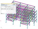
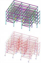
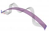
Example of the usage of linear stability calculation for arch bridge modelled as 1D frame.

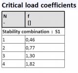


Example of the usage of linear stability calculation for arch bridge modelled with shell elements.

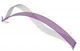
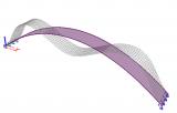
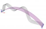
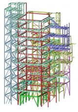
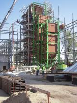
Example: Stability analysis of a steel structure for biomass boiler and service platforms - Elblag, Poland; Bilfinger Babcock CZ s.r.o.

Vyzkoušejte SCIA Engineer sami
Objevte, jak vám náš software a naše služby mohou pomoci zefektivnit vaši práci. Vyzkoušejte zdarma 30-denní zkušební verzi.
Stáhnout plnou 30-denní zkušební verzi