Highlights
- Support of 9 cross-sections in this module
- The analysis can be carried out for a linear or a non-linear combination.
- Possibility to create user-defined concrete grades
- This module takes into account the time dependent effects by computing the flexural stiffness
- ULS check includes pure axial, combined axial plus uniaxial bending, combined axial plus biaxial bending, longitudinal shear check, transverse shear check
- Possibility to have a detailed output with all intermediate calculations and used clauses
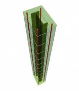
The module Composite Steel-Concrete columns EC4 is a module for structural design and code-checking of composite columns. It calculates their strength, stability and stiffness in accordance with EN 1994 for buildings.
Several checks are performed according to the ultimate limit state: resistance of members in axial compression, combined compression and uniaxial bending, combined compression and biaxial bending and influence of transverse shear on resistance to bending. Furthermore, the resistance calculation of a composite column in a fire situation is included in this module too.
Composite columns composed of concrete-filled steel tubes (CFT) have become increasingly popular in structural applications around the world. This type of column can offer many advantages, such as high strength, ductility, and large energy absorption capacity, as well as increased speed of construction, positive safety aspects, and possible use of simple standardized connections. Furthermore, today's possibility to produce concrete grades with higher compressive strengths allows for design of more slender columns, which results in larger floor space.


Composite Column Sections
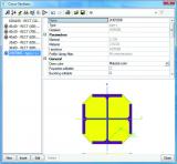
Design checks can be carried out for six rolled or welded types of composite sections as illustrated in the image below.
Methods of analysis
Composite design checks can be carried out for both a linear and a non-linear combination. Parameters involved in the check that are unique to linear / non-linear combination are discussed for both type of calculations.
Linear combination
- Second order effects: The applicability is checked according to clause 5.2.1(3) of EC-EN. If applicable, these are incorporated in accordance with clause 6.7.3.4(5).
- Member imperfection moments: The influence of geometrical and structural imperfections is taken into account through the equivalent member imperfections as mentioned in table 6.5.
- Modified moment: The moments obtained from the linear static analysis are modified on the basis of the second order moments and imperfection moments are calculated as stated above.
Non-linear combination
- Second order effects: these are not taken into account in the non-linear calculation
- Member imperfections: If the non-linear analysis is carried out without considering the imperfections in the analysis then these imperfections are accounted for in the design check in accordance with Table 6.5; else if the non-linear analysis is carried out considering the imperfections then these imperfections do not form a part of the design check.
- Modified moment: The moments obtained from the non-linear analysis are modified by adding the imperfection moments if the same are not incorporated in the analysis.
- Axial check: It must be noted that in the case of an axial check for a non linear combination, no separate buckling check is carried out. That means that the axial resistance is taken as the plastic moment of resistance of the composite section (obtained as described in section 4.1.1 below) and the corresponding utilization is defined as the ratio of axial force at the section to the plastic resistance to compression.


Design checks: Ultimate limit state
The checks are performed according to EN 1994-1-1:2004.
The design checks for composite column sections are based on the simplified method of design which is applicable to prismatic column sections with doubly symmetric sections. Different checks are performed.
Resistance of members in axial compression
This type of check contains:
- The plastic resistance to compression of the composite section
- Calculation of the elastic critical normal force
- Calculation of the effective flexural stiffness
- The influence of long-term effects: reduction of the modulus of elasticity of concrete
- Use of European Buckling curves
- Calculation of non-dimensional slenderness
- Evaluation of the buckling resistance to compression
- Calculation of the utilisation ratio for the resistance in axial compression
Combined compression and uniaxial bending
The resistance of a member to combined compression and uniaxial bending is evaluated by means of an interaction curve (clause 6.7.3.6)
Combined compression and biaxial bending
The resistance of the section under combined compression and biaxial bending is evaluated according to clause 6.7.3.7 equation 6.47.
Influence of transverse shear on resistance to bending
The influence of transverse shear forces on the resistance to bending and normal force is considered when determining the interaction curve as per clause 6.7.3.2(3)
Shear resistance
Longitudinal shear at the interface between concrete and steel is verified in accordance with clause 6.7.4.3
Design checks: Fire exposure
For the fire resistance calculation refer to EN 1994-1-2:2005 .
Following are the calculation models used to check the resistance of a column in a fire situation:
- Fully concrete encased sections: Check in accordance with the Tabulated data in Table 4.4
- Partially concrete encased sections: Balanced summation model as described in Annex G.
- Concrete filled circular hollow sections and concrete filled rectangular (or square) hollow sections: Generalised design method as described in clause 4.3.5.1 as well as the alternative design method described in Annex-H
Required modules:
- sen.00

Want to try SCIA Engineer yourself?
Explore how our software and services can help you optimise your work and boost your productivity. Try it for yourself with a free 30-day software trial.
Download a free 30-days full trial