Provided reinforcement for 2D members
Get a faster insight into your design and streamline your communication with a draftsman with the clear and visual presentation of reinforcement in 2D members in SCIA Engineer.
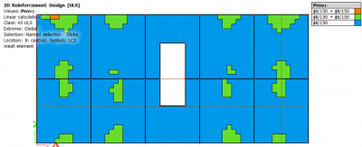
Since SCIA Engineer 19.0 there is the option to display isolines with the diameter and spacing of provided reinforcement to give you an instant understanding of your reinforcement design. Furthermore, if the amount of basic and additional reinforcement is not sufficient to cover the required reinforcement, it will be displayed in the legend.

This expands on the functionality of previous versions of SCIA Engineer, where designed areas of provided reinforcement depicted the exact area of reinforcement in square millimetres.

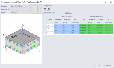
In the provided reinforcement template, adjust the basic reinforcement used across the whole 2D member. You can define either the diameter and spacing of bars, or you simply pick one mesh from the built-in library of manufactured reinforcement meshes.
For the additional reinforcement, you can opt for one of the below options:
- A fixed number of bars of a specific diameter and spacing
- Variable diameter and fixed spacing
- Fixed diameter and variable spacing
This additional reinforcement is then placed only in those regions of the 2D member where the basic provided reinforcement is not sufficient to cover the required reinforcement.
Combining the above-mentioned principles allows you to define a reinforcement in the 2D member that meets your requirements. The defined and verified provided reinforcement is then used in checks of crack width, code-dependent deformations and punching.