Tekla Structures to SCIA: rotations and eccentricities
Both in SCIA Engineer an Tekla structures, some properties are used to define the position of an element. Those properties are taken into account both from SCIA Engineer to Tekla Structures as well as from Tekla structures to SCIA Engineer.
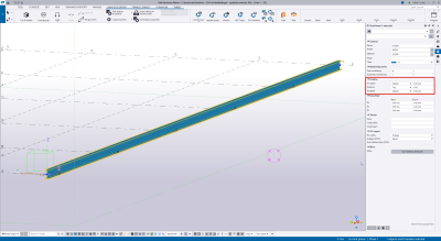
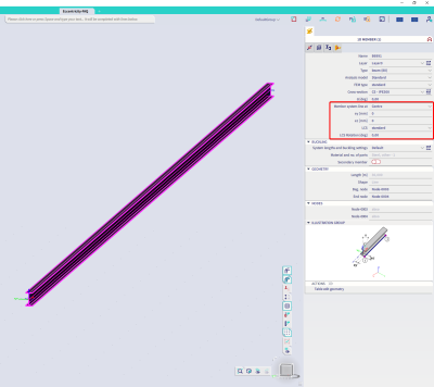
The properties will be linked as follows:
- The property 'on plane' in Tekla Structures is linked to the location of the system line in SCIA Engineer. A user value which would be defined in Tekla structures, is taken into account in SCIA Engineer as a value for ey.
- The property 'Rotation' in Tekla Structures is linked to the LCS Rotation in SCIA Engineer. A user value which would be defined in Tekla Structures is added to the option 'front', 'top', 'back' or 'below' to define the LCS Rotation in SCIA Engineer.
- The property 'At depth' in Tekla Structures is linked to the location of the system line in SCIA Engineer. A user value which would be defined in Tekla Structures, is taken into account in SCIA Engineer as a value for ez
The position of each member will thus be taken into account and can be exported from Tekla structures to SCIA Engineer and imported from SCIA Engineer into Tekla structures. The linked properties will be modified according to the selected cross-section and profile. Keep in mind that the orientation of a profile in Tekla structures is not necessarily the same as the orientation of a cross-section in SCIA Engineer. Therefor, the position properties of two different cross-sections can be exported differently to take this into account.
This can be clarified with a small example. Below you find a T-section and an I-section in Tekla structures. Both of them have the same orientation. The element is moved to the right with the value 'on plane', the rotation is defined as 'top' which means that the profile is not rotated and the element is positioned downwards with the property 'depth'.
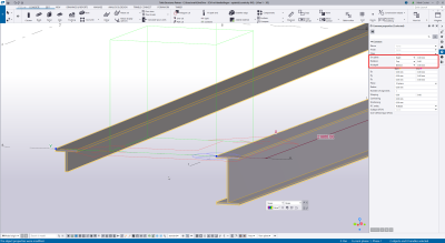
The position of the members is correctly taken into account. Nevertheless, when both members are selected in SCIA Engineer it is visible that the position properties are different.
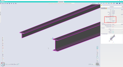
For the T-section, you will find that the element is rotated 180° and that the system line is located on the bottom right. If we check the orientation of the cross-section in SCIA Engineer and the profile in Tekla structures, this is indeed different. This difference is correctly taken into account and the position of the element is the same in both programs.
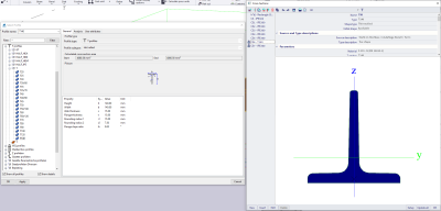
The orientation of the selected I-section is exactly the same in Tekla structures as in SCIA Engineer. Therefor the element with the I-section is not rotated in SCIA Engineer and the system line is located at the top left.