3D results
Displacements and stresses can be displayed on the 3D rendered surface of columns and beams. The results can also be projected on the initial as well as the deformed structure. This can give you even better insight into the global behaviour of the structure.
The 3D results are accessible via Main menu > Results or in the Results workstation of the Process toolbar:

3D deformations
Available values are:
- u_x, u_y, u_z: displacements of fibres, in the member local coordinate system
- φ_x, φ_y, φ_z: rotations of fibres, in the member local coordinate system
- U_total: resultant displacement of fibres, i.e. U_total = √(u_x²+u_y²+u_z²)
3D stresses
There are three available types of magnitudes:
- Basic magnitudes (in local coordinate system of finite elements)
- Principal magnitudes (including σ_E = von Mises stress)
- Membrane magnitudes (only for 2D members)
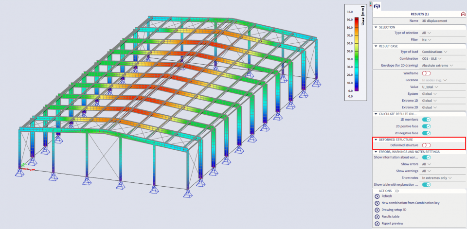
These 3D results may be displayed on the original or on the deformed structure of the members.
Deformed structure
When the ‘Deformed structure’ is selected, together with the envelope combination or a result class, also the type of ‘Member deformation’ needs to be selected:
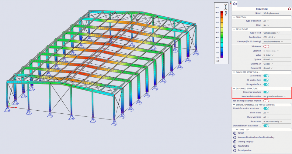
- For global maximum: The rendered surface is displayed as it deforms under the load the load combination that causes the extreme value of the selected magnitude on the whole structure. The evaluation is done for one single critical combination, resulting in a continuous deformation.
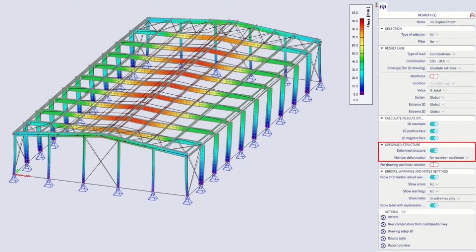
- For member maximum: The rendered surface is displayed as it deforms under the load combination that causes the extreme value of the selected magnitude on the member. The evaluation is thus executed for each member separately. For every member the extreme may be caused by another critical combination, therefore discontinuities in connecting nodes may occur.
Initial structure:

Deformed structure for global maximum:

Deformed structure for member maximum:
