Perform a steel SLS check
In order to perform a steel SLS check, the following data needs to be specified:
- The span of the elements to be checked
- The deflection limits of the elements to be checked
- The camber attributed to the elements (optional)
The span, deflection limits and camber values can be all input via the buckling setting dialog, which can be accessed via the properties dialogue of an element.
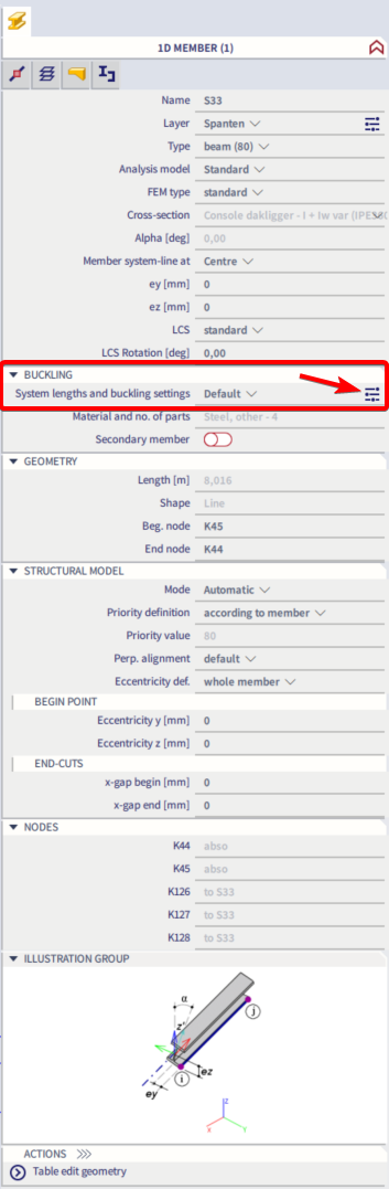
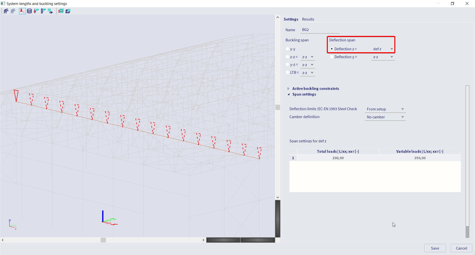
Set the elements span
The spans of 1D elements (beams, columns) can be set (independently for local Z and Y directions) via the buckling setting dialogue as highlighted in the picture below.
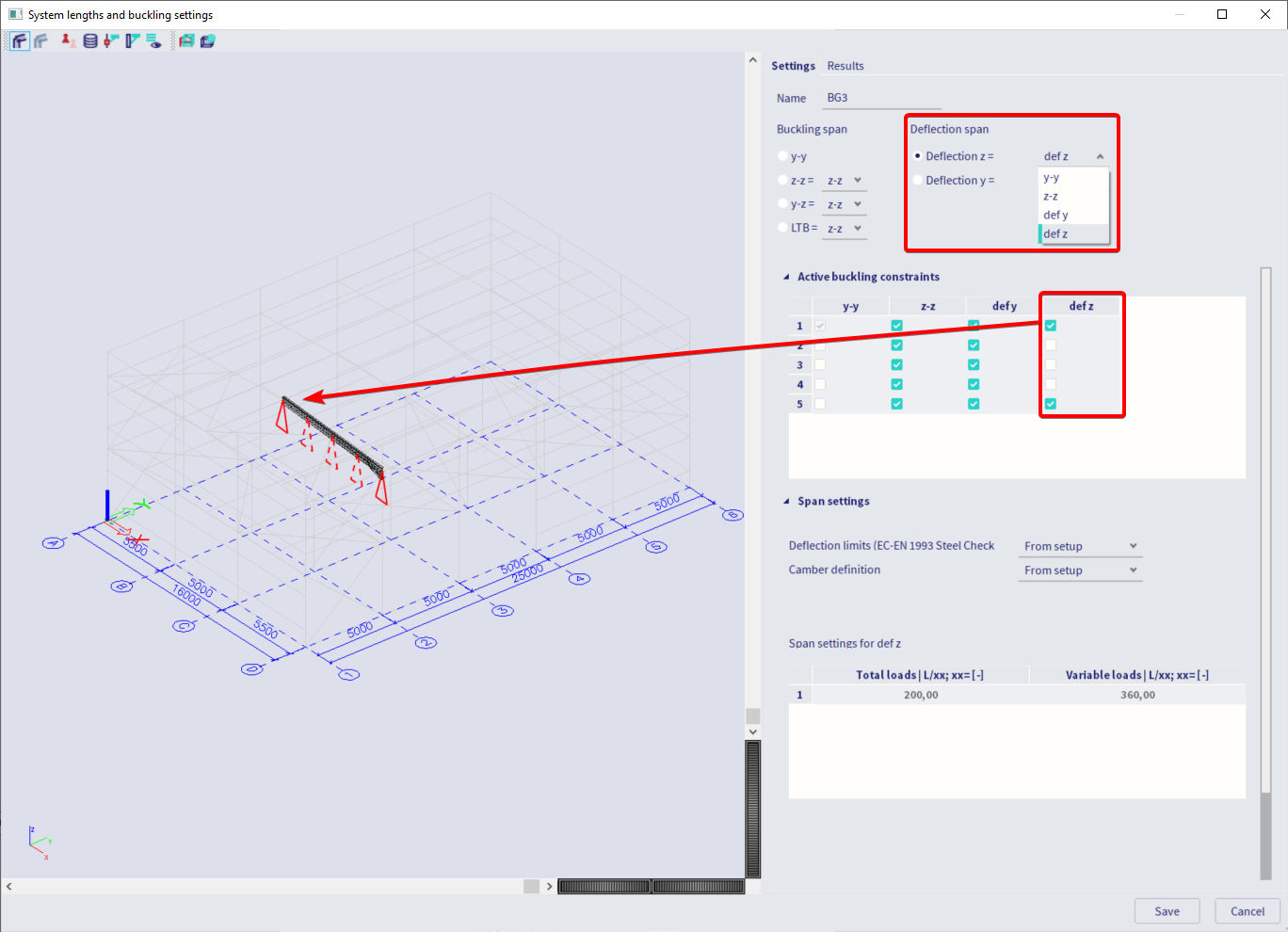
To set the span independently for the local Y and Z directions, one needs to select deflection z = defz and deflection y = defy.
However, the dialogue also allows you to specify that the deflection in one direction is based on another deflection/buckling setup already entered. For instance, when selecting deflection z = y-y, it means that the setup for the deflection in the Z direction will be the same as the setup for the y-y buckling. If, on the other hand, you select deflection z = defy then the setup for the deflection in the Z direction will be the same as the setup for the deflection in the Y direction (deflection y).
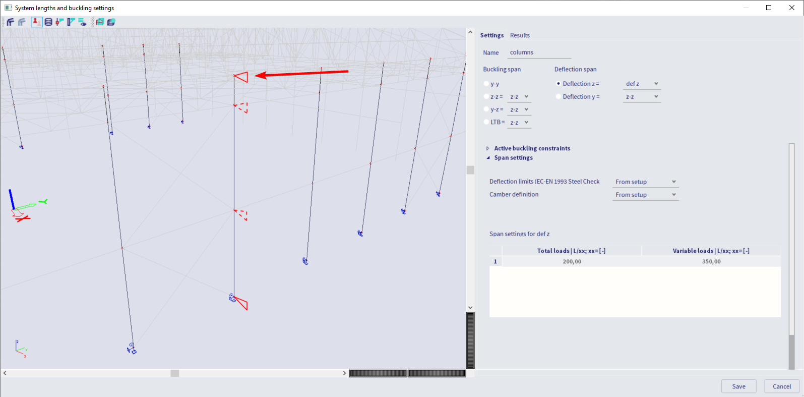
If you select for instance deflection z = defz, deflection supports can be enabled/disabled (dotted triangle means a disabled support) by clicking on the red triangles in the graphical window. The same result can be achieved by ticking/unticking the check boxes in the “Active buckling constraint” section of the dialog. The deflection supports can be set (enabled/disabled) only in elements’ nodes.
Set the deflection limits
The deflection limits can be set in the “span settings” part of the dialogue, figure 3. The deflection limits can be set independently for the local Y and Z directions (based on the active deflection option, defy or defz, see paragraph above), and independently for total loads and variable loads.
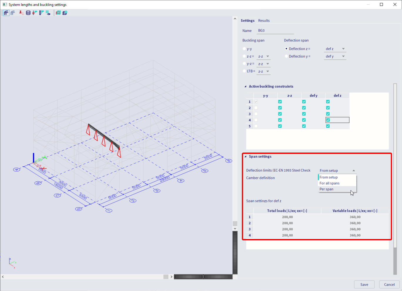
Three options are available:
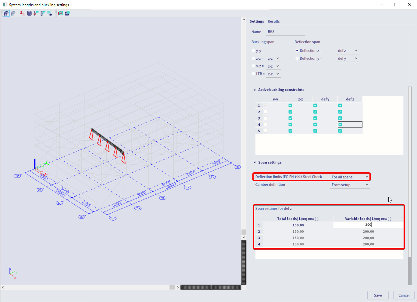
- For all spans: the same deflection limits will apply to all the spans of the selected element(s).
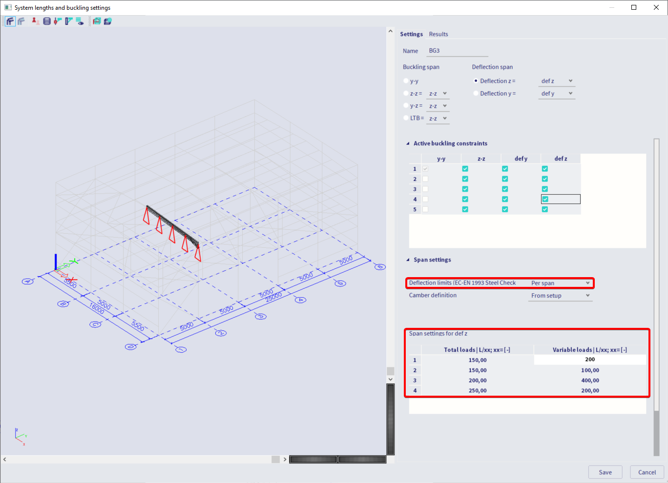
- Per span: different deflection limits will apply to different spans.
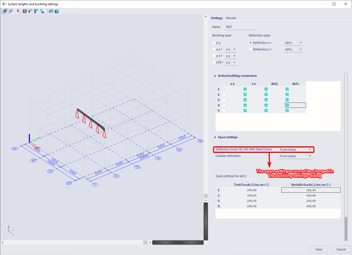
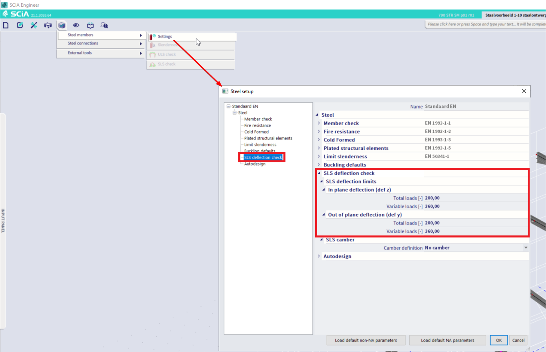
- From setup: the deflection limits specified in the steel setup will apply to all the spans.
Note that a span is defined as the distance between two active deflection supports (solid line triangles in the graphical window). If you want to define a continuous span for a selected element, then all the intermediate deflection supports must be disabled.
Set the camber
The camber can be set independently for the local Z and Y direction (based on the active deflection option, defy or defz, see paragraph about the span setup) via the combo box.
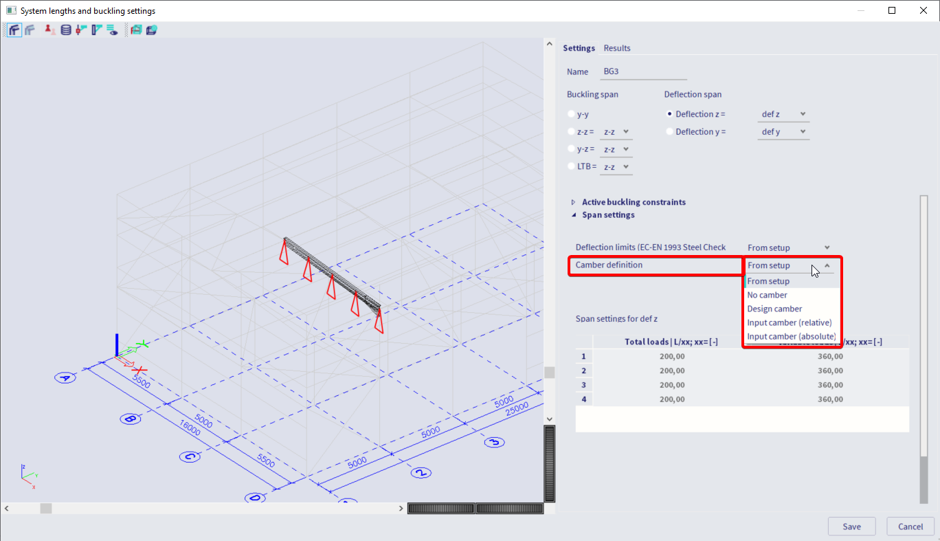
Four options are available:
- No camber: no camber will be applied
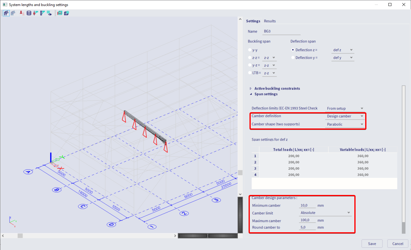
- Design camber: the camber can be designed based on the deflection limits. You can define certain boundary conditions (camber shape, minimum camber, camber limit, maximum camber and rounding)
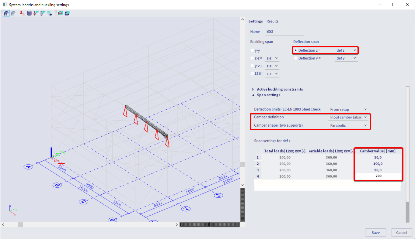
- Input camber (absolute): the camber value will be input, span by span, in absolute dimensions (length units).
- Input camber (relative): the camber value will be input, span by span, as a relative coordinate (1/length units)
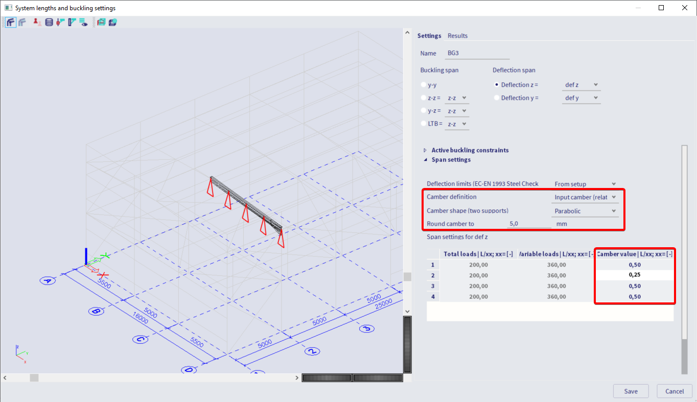
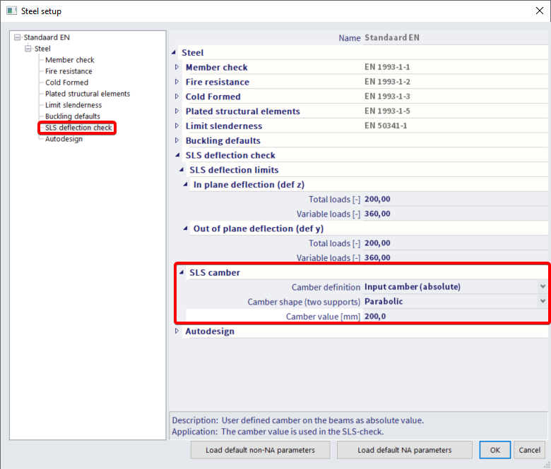
- From setup: the camber values specified in the steel setup will be applied to all spans (figure 9).
Note: The camber is defined with respect to the local z axis. If the local z axis is directed downward, you have to input a negative value in order to have an upward camber.
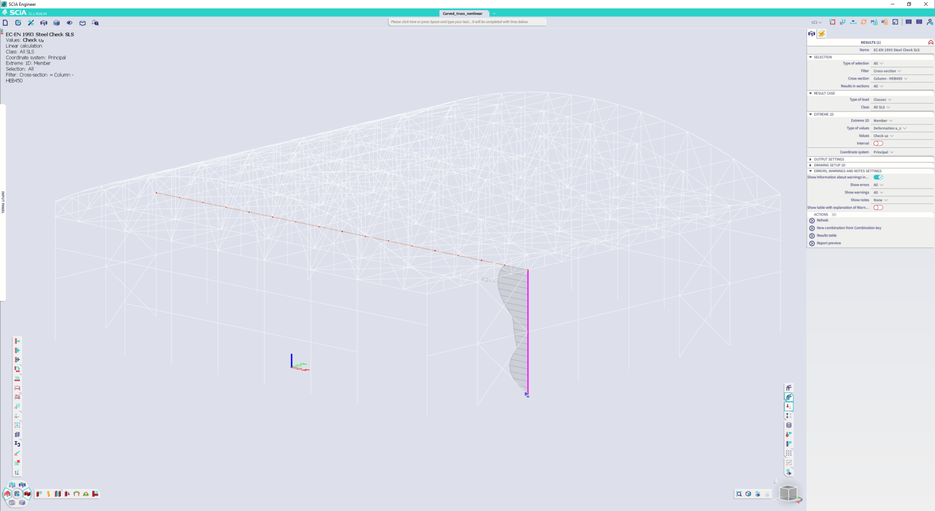
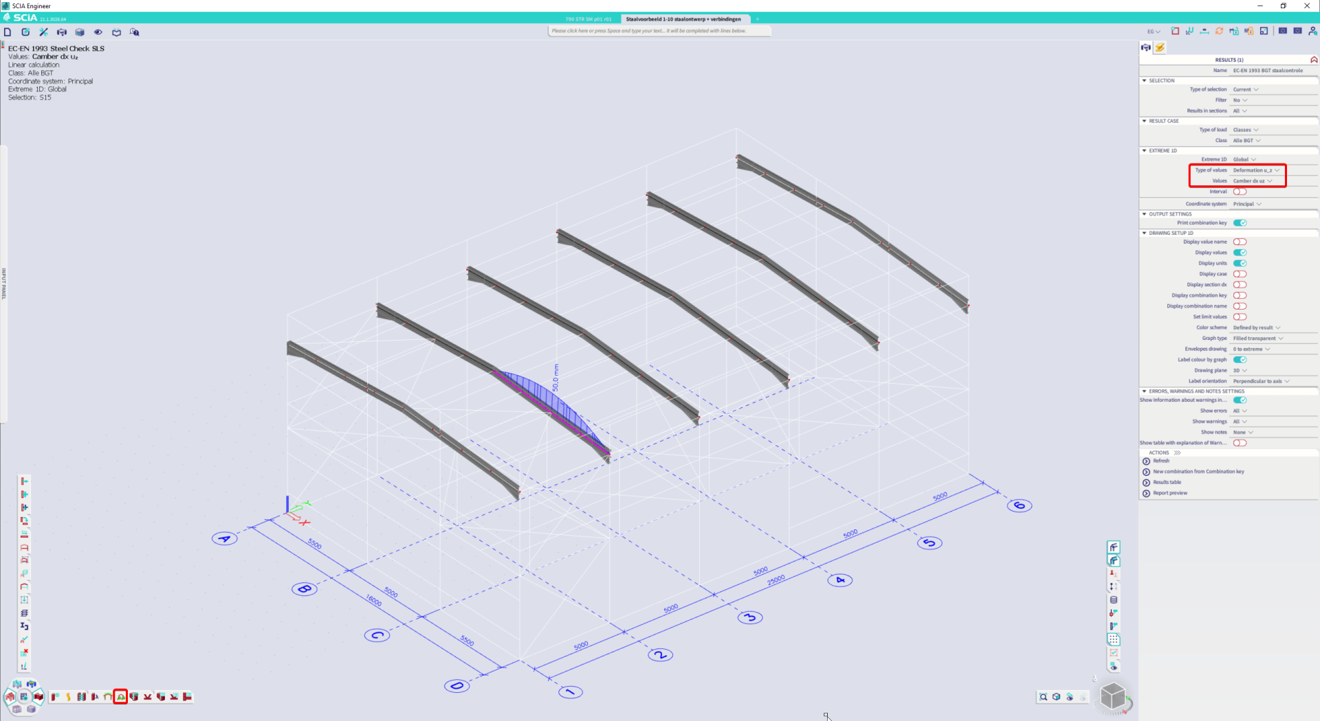
Visualize the defined camber
The specified camber can be visualized via the SLS check menu. The figures show the camber input and the visualization. Note that one continuous span has been defined for the selected beam (solid line triangles only at the element ends).

correctly set the span for a cantilever beam
In order to obtain correct results, cantilever condition should be specified in the buckling settings by disabling all span supports except the support at one of the beam ends.
Note how the cantilever condition is correctly specified using the span definition (one support enabled, solid triangle).
If such setup is not respected, for instance span supports are kept active at both ends, the deflection is not correctly computed for the cantilever element.