Second order analysis
Second order analysis takes into account how the structure deforms while loads are being applied on it. Numerically speaking, all load is divided into smaller portions and for each load portion, the stiffness of the structure changes.
Second order effects are also called P-Δ and p-δ effects, and in SCIA Engineer (among other places) these effects are also referred to as Geometrical nonlinearity.
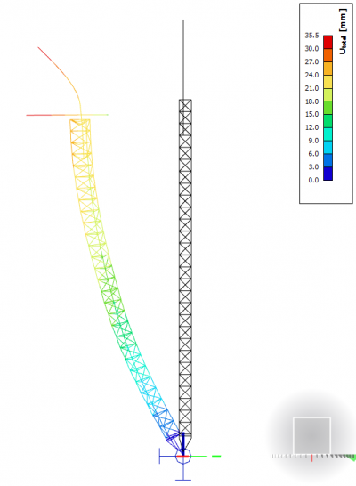
Here are some common questions from users that our Support team often needs to address.
When do I need to perform a second order analysis?
Material-specific Eurocode parts (EC2, EC3, EC4, EC5, etc.) specify in their chapter 5 (Structural analysis) when to perform a second order analysis. For steel structures, low values of the αcr coefficient indicate high flexibility (or slenderness) of the structure, and therefore, high sensitivity to initial imperfections and lateral displacements.
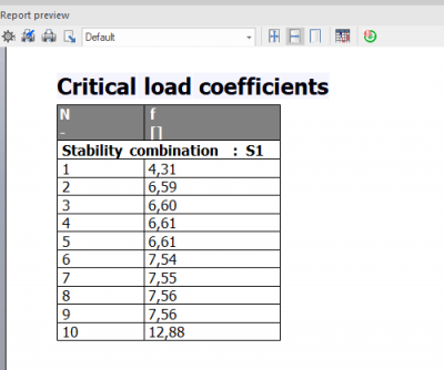
The αcr coefficient is determined by dividing the elastic critical buckling load for a global instability mode, Fcr, by the design loading on the structure, FEd. In order words, we need to rely on the results of stability analysis to find out IF we need to perform second-order analysis or not.
What we can do in SCIA Engineer is create stability combinations from selected design combinations and obtain the critical buckling factors that correspond to these loading scenarios. These factors are simply multipliers of the load that is present in the stability combination. And because our stability combinations are the “design load”, these factors are exactly the αcr coefficients that we are looking for.
It is also important what kind of FEM analysis of the structure we would like to perform to obtain the design internal forces: are we going to stick to elastic analysis, or would we also like to make use of plastic hinges to redistribute moments? According to EC3, when we perform elastic analysis and any of our αcr are lower than 10, then we need to design the structure using second-order analysis results. In the case of plastic (e.g., hinge) analysis, any αcr dropping below 15 indicates the need to go to second-order.
How can I insert global imperfections according to the code?
Geometric imperfections in a FE model make sure that second-order effects are properly triggered during a nonlinear analysis. The ones familiar with Chapter 5 of EC3 often ask how to take global or member imperfections into account in SCIA Engineer.
Imperfections are defined on the level of a nonlinear combination: each nonlinear combination can have its own set of imperfections. This is useful, because different loading scenarios induce different failure modes, which in turn are influenced to a higher or lesser extend by a specific imperfection shape.
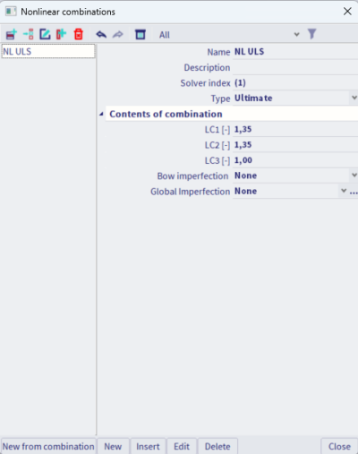
Global imperfections are defined and stored in a specific Library which can be accessed directly from the nonlinear combinations dialog or via Libraries > Load cases, Combinations > Global imperfections.
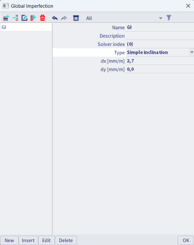
To define a global imperfection as a uniform sideways tilt of the structure, use the input type called “Simple inclination” and define the relative inclination along the global X and Y axes, dx and dy. In EC3, a formula is given in Chapter 5.3.2, Figure 5.2 for the angle of the inclination, φ. In the input fields in the nonlinear combination dialog, use dx = 1000*φx (or dx = 1000*tan(φx), depending on how you interpret the figure). The Simple inclination imperfection type is perfect for structures regular in plan and height.
Are there different input possibilities for global imperfections?
Yes, a couple of them are possible in SCIA Engineer. Namely:
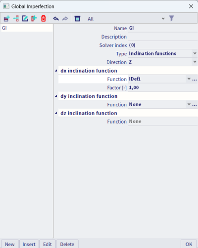
- Inclination functions: if you would like to vary the inclination value and even sign along the height (or length) of a structure, you can use imperfection functions. These functions are manually defined multilinear curves, and are inputted and stored via Libraries > Structure, Analysis > Initial imperfections.
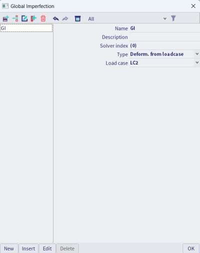
- Imperfections based on a load case: SCIA Engineer can calculate the deformation of a structure for a load case you specify, and apply this deformation as an initial imperfection. If you know what imperfection shape you more or less would like to obtain, you can define a load case that would cause such deformation; you may define a load case with a fraction of all design loads; in this way, you are certain that all possible stability effects will be represented in the analysis.
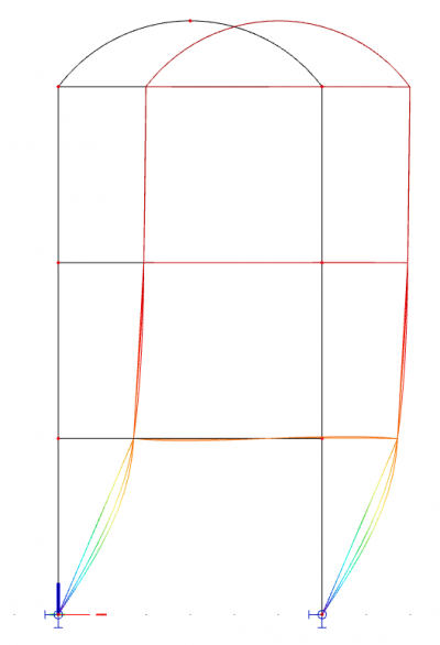
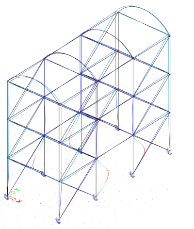
- A stability eigen shape as an imperfection: you can select a stability combination and one of its buckling shapes to apply as an imperfection on the structure.


How can I insert the local imperfections according to the code?
As mentioned above, imperfections are assigned per nonlinear combination. The most practical way to assign the value of imperfections is to refer (via the settings of the combination) to the buckling settings. This lets one specify, via the buckling systems, which members should have imperfections: it is often practical to consider imperfections on specific members that we would like to investigate in more detail, rather than assign imperfections to all members in the structure.
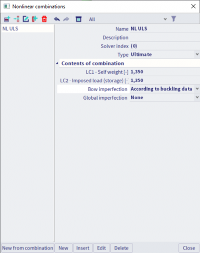
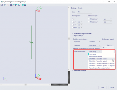
Are there different input possibilities for local imperfections?
Yes. Instead of referring to buckling data, SCIA Engineer lets you define local imperfections directly via the properties of the nonlinear combination. Keep in mind that the specified curvature there will then be applied to all members in the structure.
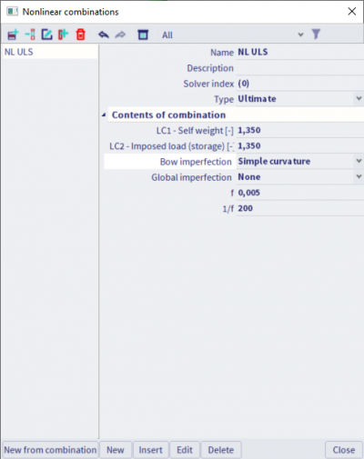
What does the functionality 'Geometrical nonlinearity' mean?
Geometrical nonlinearity refers to a second-order calculation. When you execute an analysis while this setting is turned on, the structure will be deforming as load is being applied and the load steps and numerical method for nonlinear calculation will be taken as defined in the Solver Settings. Therefore, results will be different to a linear analysis, regardless if initial imperfections are applied or not. However, to properly capture important nonlinear effects, it is advisable that imperfections be used.
Note: Geometrical nonlinearity is taken into account in nonlinear analysis, which is in turn executed for nonlinear combinations. Second order effects are not present in the linear analysis results: linearly solved load cases are superposed to obtain the results of linear combinations. In nonlinear context, the principle of superposition does not apply, because the effects of loads influence the effects of other loads.
How should I calculate the imperfection amplitude when using a buckling shape as imperfection?
Frames
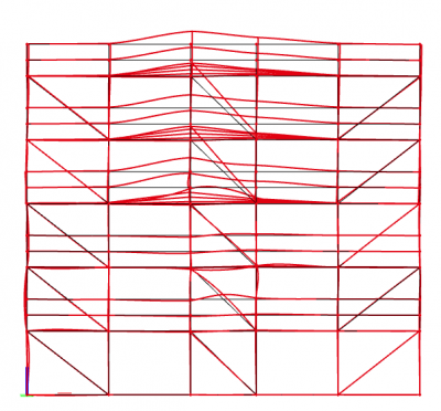
EN 1993-1-1 gives guidance in §5.3.2 (11) on how to calculate the amplitude of a unique imperfection shape derived directly from stability analysis (ηinit). This method is valid for frames, and requires that the you derive the amplitude manually and input it in SCIA Engineer. The choice of an imperfection shape is also up to you.
This method of managing imperfections requires that you define a load combination for the stability analysis itself and visually review the obtained instability checks. You should select the lowest critical buckling shape that represents the overall deformation of the structure in the direction being investigated in the nonlinear load scenario that will follow. The instability shape and its amplitude are again inputted per nonlinear combination.
For the derivation of the imperfection amplitude, you would have to obtain a few inputs from the FE model, from linear and stability analysis results, as well as from the Steel Code Check.
The imperfection is derived as follows:


With:
- ηcr: the shape of the elastic critical buckling mode, hence, the term before it is the amplitude value
- λ: the relative slenderness of the whole structure
- χ and α: reduction and imperfection factor, as derived for the critical section; these can be taken from the Steel Code Check
- αult,k: a factor which, if applied on the loads in a linear scenario, would make the most compressed member reach its characteristic section resistance NRk
- αcr: the elastic critical buckling factor for the stability combination and selected buckling shape. For consistency, the stability combination should contain the same loads as analysed in the nonlinear combination
- MRk: the characteristic moment resistance of the critical cross-section, calculated for the relevant section class
- NRk: the characteristic axial force resistance of the critical cross-section
- EIη"cr,max: (whole term) is the bending moment due to ηcr at the critical cross-section
When we interpret the above, we see that we need to determine:
- the critical cross-section in the structure (where the load effects lead to a maximum utilisation ratio in linear context),
- the most compressed member in the structure.
αult,k, MRk, NRk, χ and α can be obtained from the Steel Code Check. αcr and (EIη"cr,max) can be obtained from the stability analysis results.
Plates
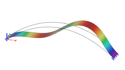
For structures modelled by 2D plate elements, a similar procedure applies, but the amplitude of imperfections should be determined from §C5 of EN 1993-1-5. Again, to properly capture all potential buckling failure modes, one should execute nonlinear analysis with second-order effects and initial imperfections.
Due to the versatility of plated element models, in theory, all failure modes can be captured with appropriate:
- meshing;
- element formulation for bending and shear;
- and inclusion of imperfections.
This is different from frame structures, where additional verifications are required for lateral-torsional and torsional buckling.
§C5 of EN 1993-1-5 essentially two possibilities for the definition of imperfections:
- a. An explicit modelling of both geometric and structural imperfections:
- geometric imperfections can be approximated as buckling shapes, with amplitudes taken as 80 % of the fabrication tolerances;
- structural imperfections (e.g. residual stresses) may be represented by a stress pattern expected from the fabrication process with amplitudes equal to the expected (mean) values.
- b. Modelling the imperfection shape and amplitude according to a simplified approach given in table C.2. In this case, both geometric and structural imperfections are represented by equivalent geometric imperfections.
Table C.2 gives amplitude values per type of component that are simple to derive. However, the chapter specifies that different types of geometrical imperfections may need to be combined together: in addition to the main imperfection, other imperfection shapes should be represented (in addition) with 70 % of their recommended amplitude value. SCIA Engineer only allows a single buckling shape to be used as imperfection: if needed, accompanying geometric imperfections can be substituted by appropriate fictitious forces acting on the structure.
